Overview
This page is dedicated to the custom power distribution system that I designed and built at home, in my spare time, for my own personal use. This was a relatively early stage in the build dating back to early 2019. At the time I knew I needed more electrical power for how I was using the vehicle so I started envisioning an end result to suit my needs, working on turning my vision into a reality. I set objectives and researched and planned what I was going to use to meet those objectives. I started calculating power draw and load-carrying capacity limits and chose electrical parts that would exceed my current needs and leave room for future expansion. From there, I put my vision onto paper and created a wiring diagram from scratch to prove out my concepts and give me a specific plan toward which to build.
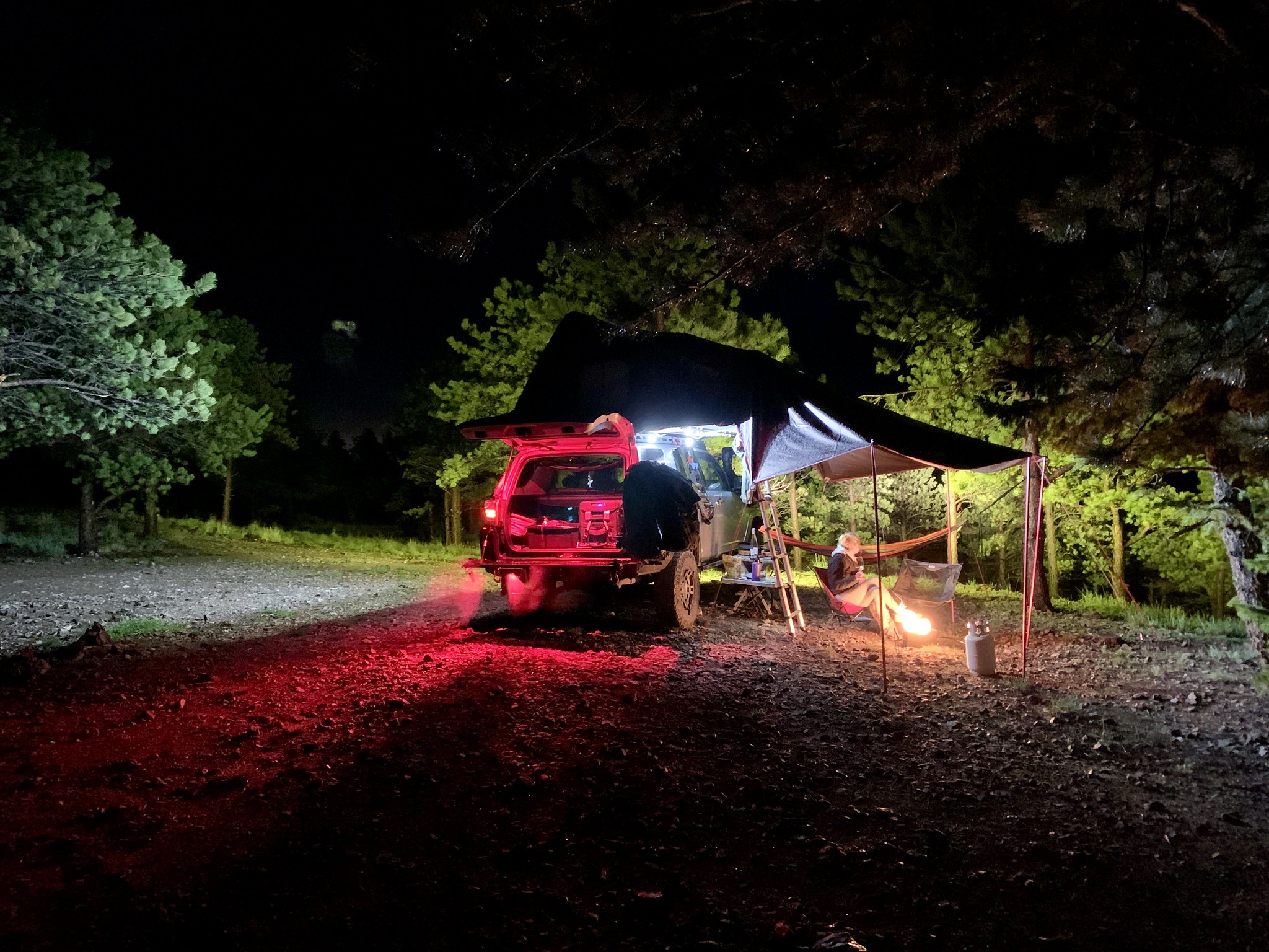
My objective was to design and build a dual battery system, in which the accessory battery is permanently isolated from the starter battery, and could be charged by solar, DC-DC charger, or an AC shore power hook up. The battery would be the power supply for a custom power distribution module and would be protected by a low-voltage disconnect. The power distribution module would power any and all non-OEM electrical circuits, most of which would be controlled by a custom switch panel in the dash. I also wanted to build a plug-and-play electrical box for the rooftop tent that would provide a 12-volt power outlet for device charging and control interior and exterior lighting. The tent interior lights would be switchable between red light, which doesn’t attract bugs or alter your night vision, and white light which provides maximum visibility. Tent exterior illumination would be provided by the roof rack-mounted flood lights.
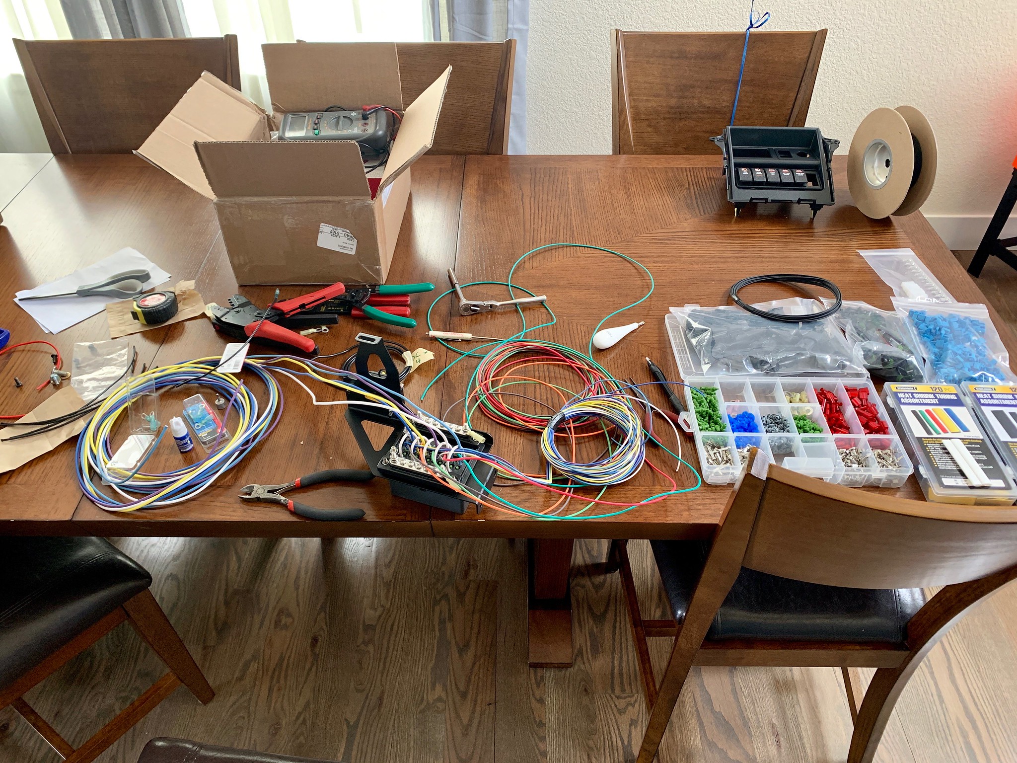
I began researching every aspect of parts, pieces, individual components, amperage requirements, amperage limits, waterproof ratings, build quality, durability, compatibility, expected life, plus bang for your buck value. From there I made a wiring diagram. This was basically my blueprint for getting all my ideas onto paper, to confirm everything I was planning was plausible and would work the way I had envisioned. I wanted to do a nice clean installation once, the first time, and a good diagram was a key factor in accomplishing that. It would also provide a reference for troubleshooting down the line if ever necessary. I got everything listed out – connectors, which wire goes to which terminal, what the wires are for, what color wiring each system uses, relay pin designations, the parts and pieces I was going to use for assembly, and the weakest link in each circuit in terms of amperage limitations so I could fuse each thing safely and appropriately. When I was satisfied with the layout and determined everything would be functional, I began the physical work.
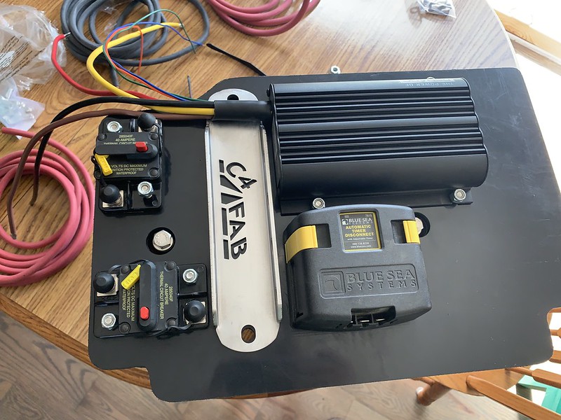
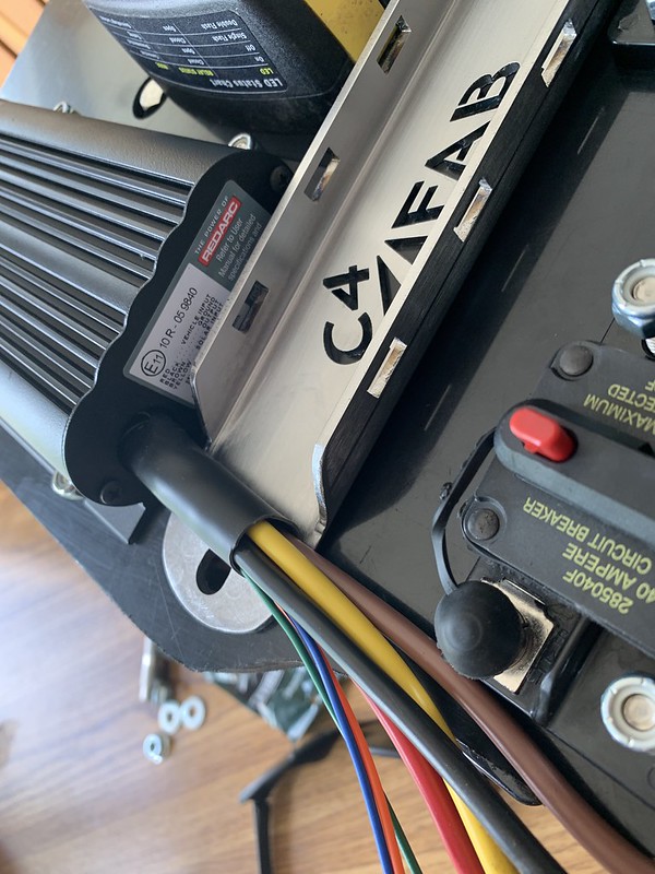
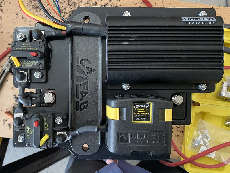
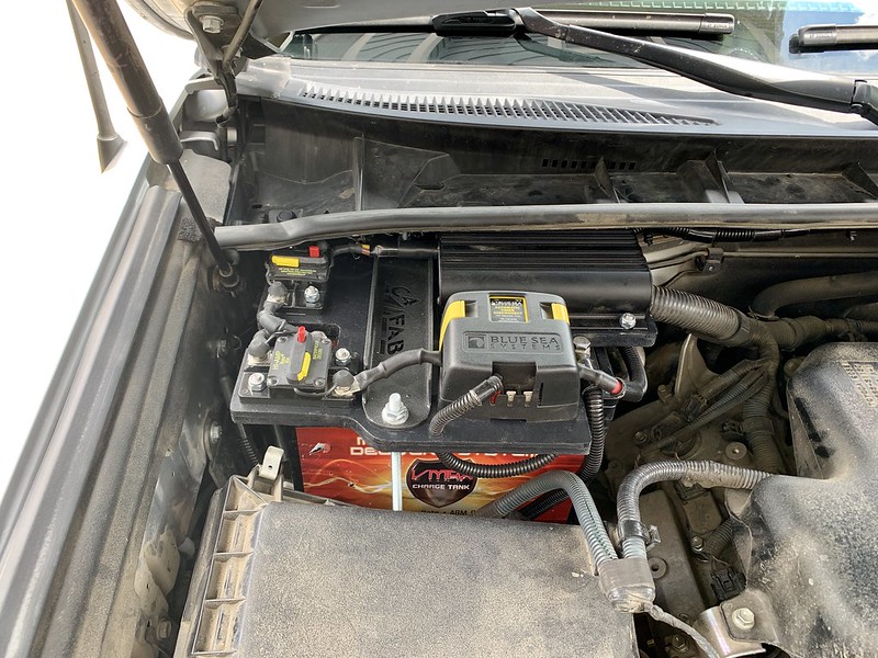
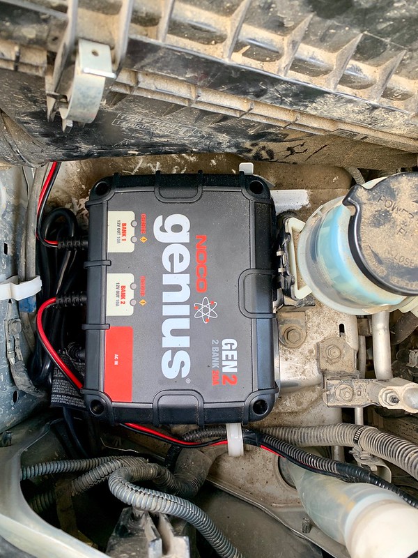
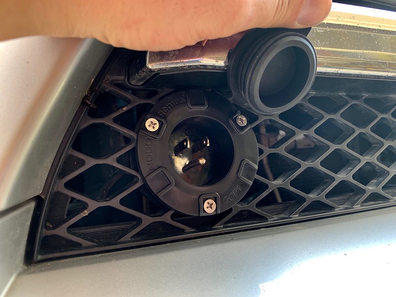
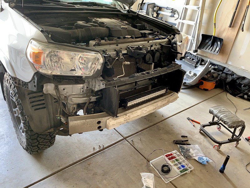
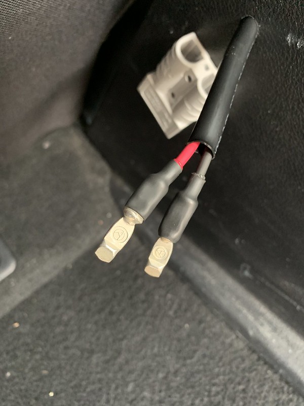
Here’s the basic rundown of the dual battery setup (shown below – Fig. 1), I created a power wire that starts from the positive terminal of the starter battery. From there it runs to a 40 amp circuit breaker and then to the red DC power input wire on the RedArc DC-DC charger. The brown power output wire on the RedArc goes to another 40 amp circuit breaker and then to the positive terminal of the deep cycle accessory battery. From the accessory battery I made another power wire that goes out to an 80 amp circuit breaker, then to the low voltage disconnect, and continues along to B+ connection at the power distribution module. Each circuit off the power distribution module has a 2 wire pigtail for power and ground. The power distribution module ground connects to chassis ground. The accessory battery negative terminal has a cable to chassis ground and a wire to ground the low voltage disconnect. The blue wire from the RedArc goes to an ignition-on reference under the dash. The orange wire is a terminated and sealed open circuit which sets the RedArc charging profile for AGM batteries. The green remote indicator LED wire is not being utilized for my application so it is also terminated and sealed. The yellow solar input wire off the RedArc goes to an Anderson plug for a secure but quick-disconnect plug-in for a portable solar panel. I installed an onboard waterproof dual bank shore power AC/DC smart charger. It connects to both of the batteries separately and when an extension cord is plugged into shore power on the front grill it will smart charge and maintain each battery individually while supplying up to 10 amps per battery as needed.
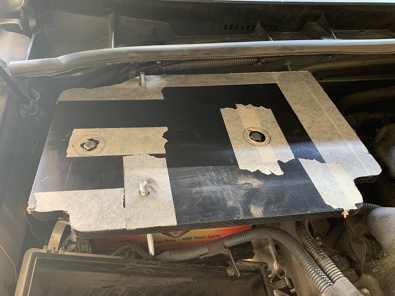
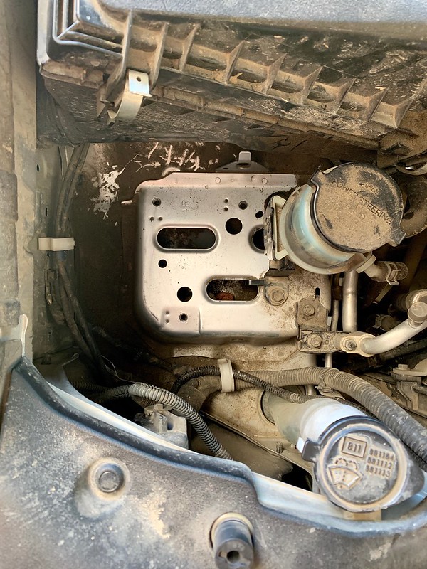
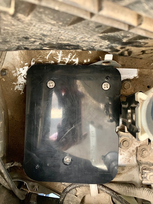
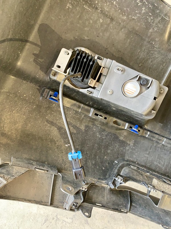
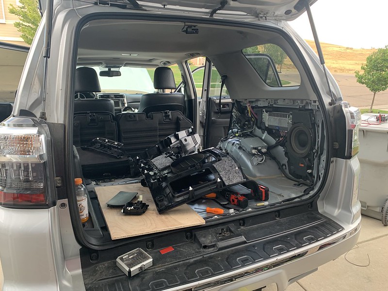
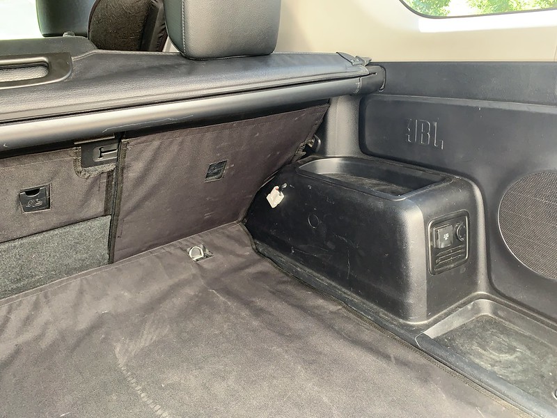
Most of the dual battery components sit on top of the accessory battery on a mounting plate I made from non-conductive half inch thick HDPE. I routed the cabling and modified the battery hold down to provide appropriate clearance. I made a second HDPE mounting bracket for the onboard AC/DC charger in the open space behind the passenger headlight.
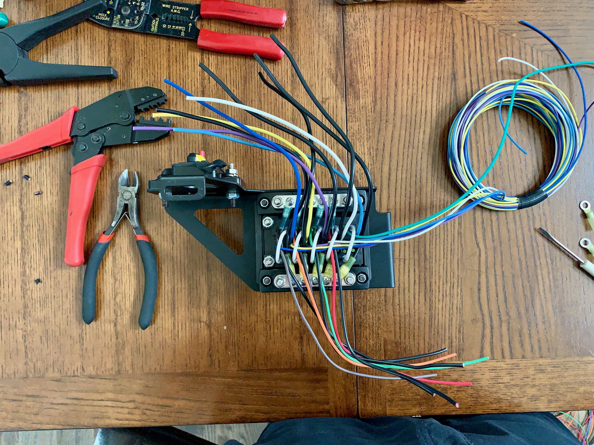
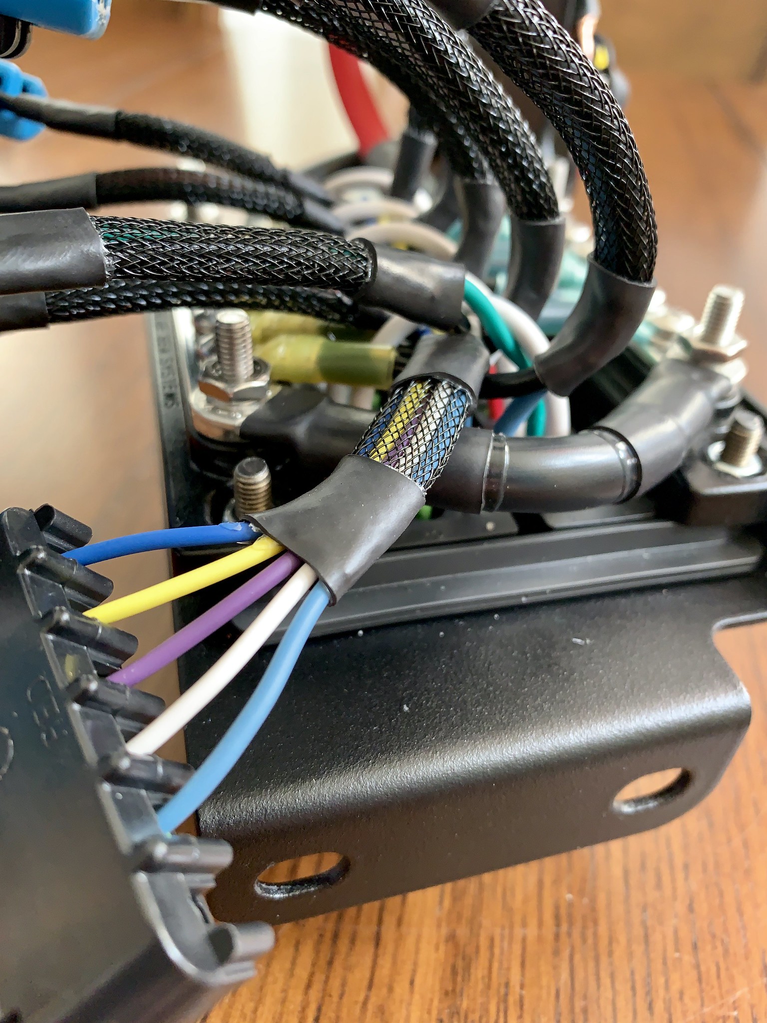
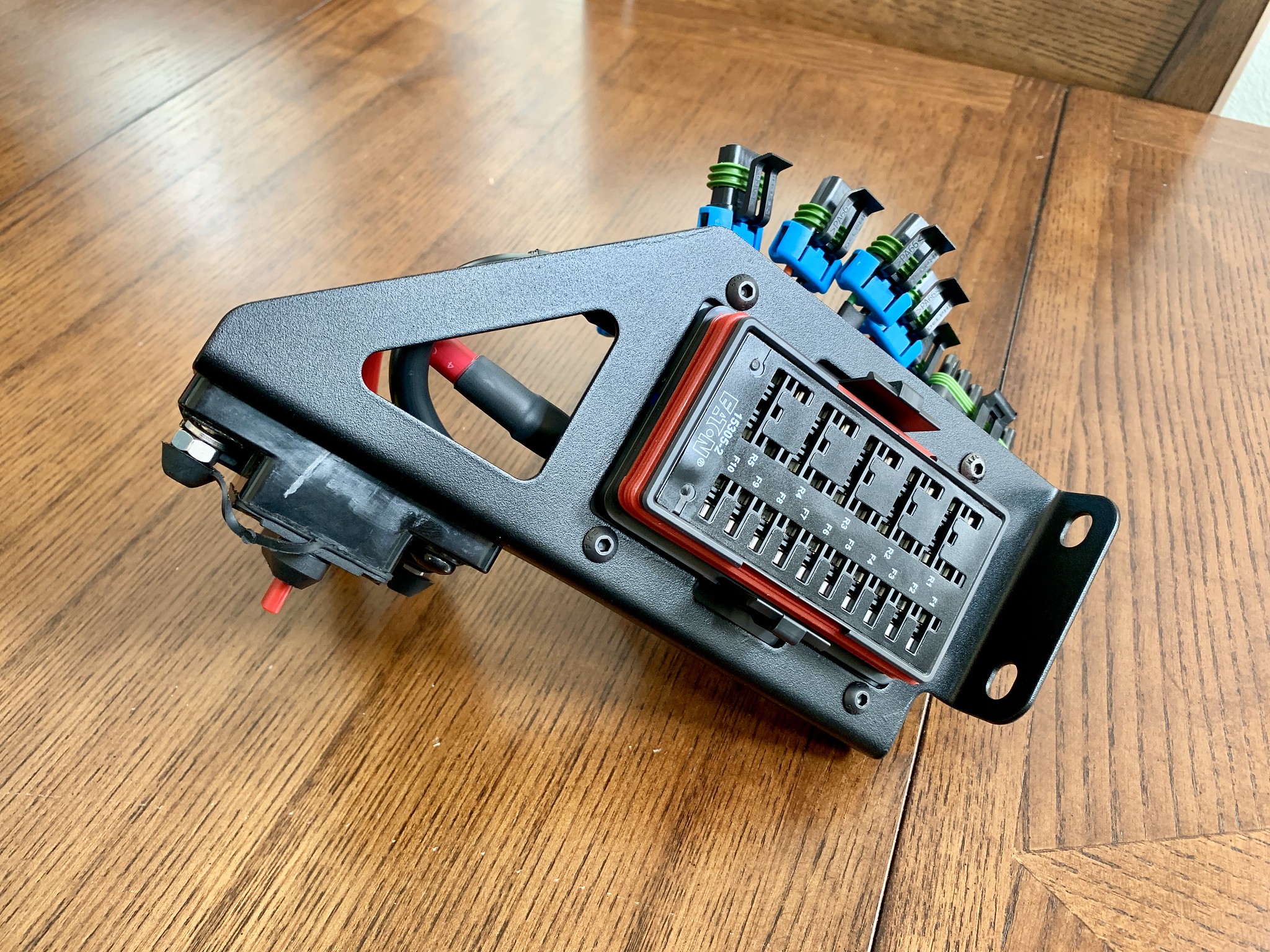
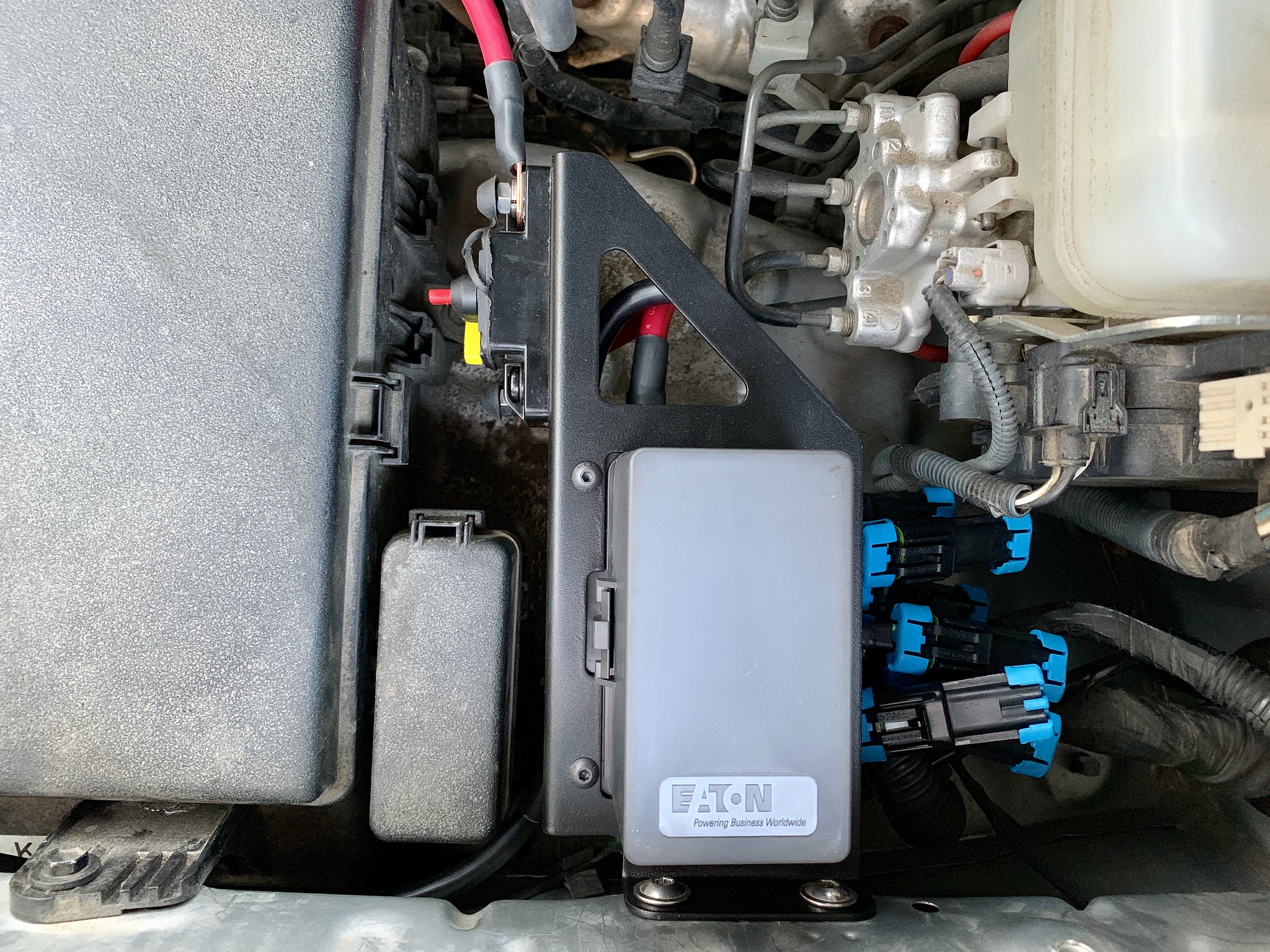
For the Power Distribution Module I started with a Bussman 10 circuit power distribution module housing mounted in a Shrockworks bracket. I modified 2 BlueSea bus bars to fit as ground points on each circuit. There are 5 fused circuits and 5 relayed circuits. I wired it all to be plug-and-play using Metri-Pack 280 Series, Delphi Weather-Pack, and Molex Mini-Fit Jr. connector housings, terminals, and seals depending on the circuit and intended use. All the wiring is type TXL Primary Wire (OEM Specification: Ford M1L-123A, Chrysler MS-8288, SAE J-1128), with marine grade dual wall adhesive lined heat shrink, ISO 280 35 amp micro relays, and ATC blade fuses.
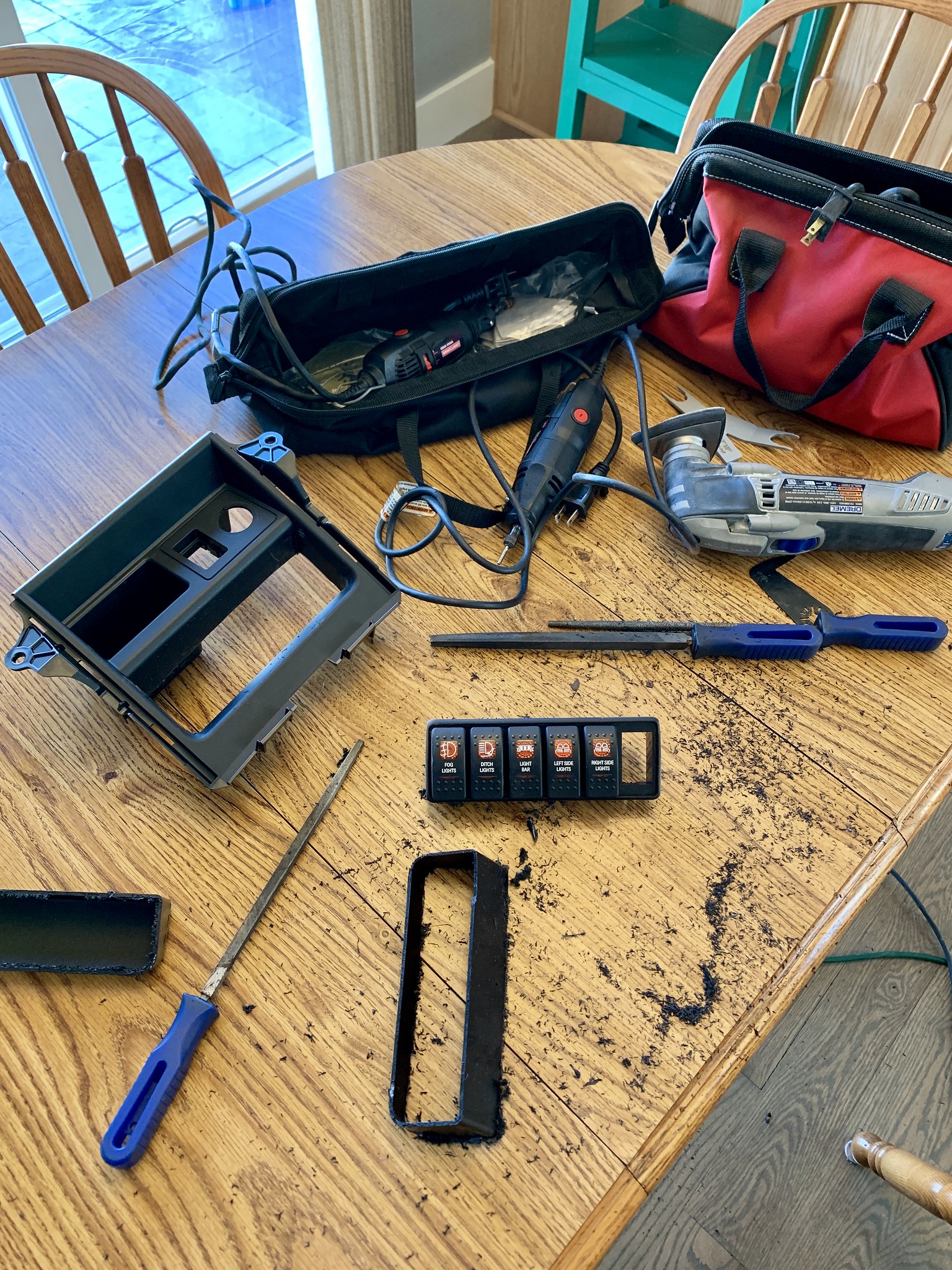
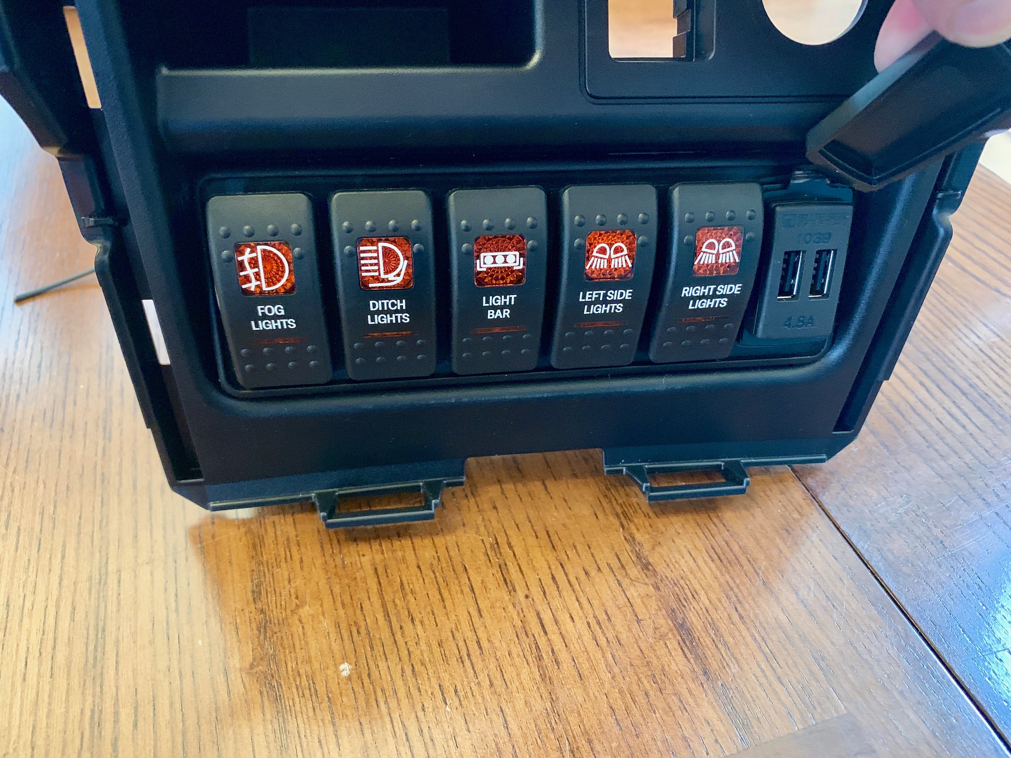
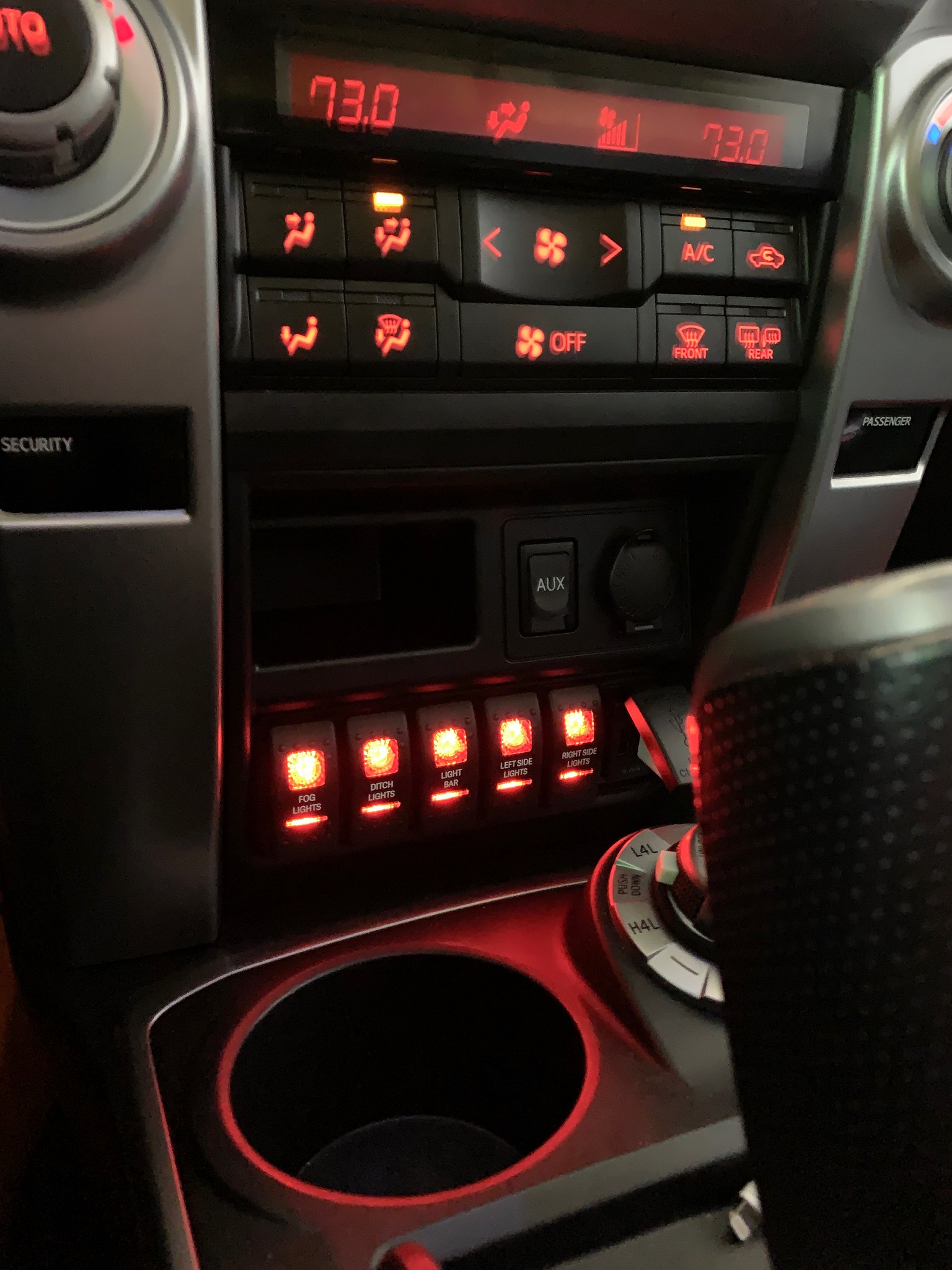
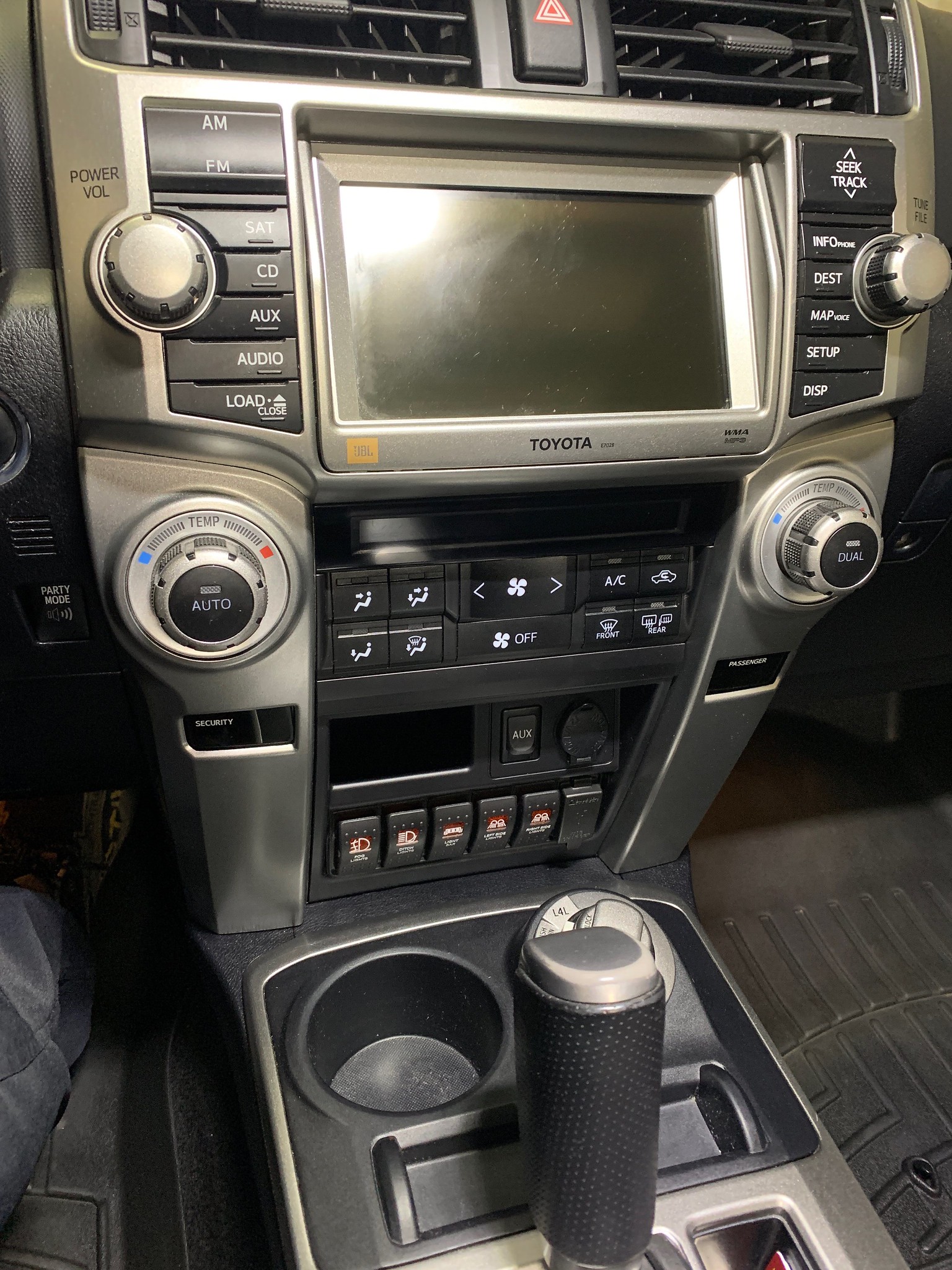
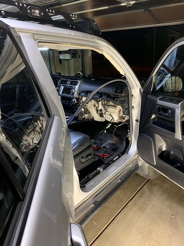
For a switch panel I picked up a new OEM dash compartment for a 2014+ 4Runner, custom Contura II switches backlit to match the OEM interior backlighting, a Blue Sea 1039 dual USB fast charger, and a blank mounting panel in which to install them, and made it all fit. The switch backlighting is a match to the factory dashboard backlighting.
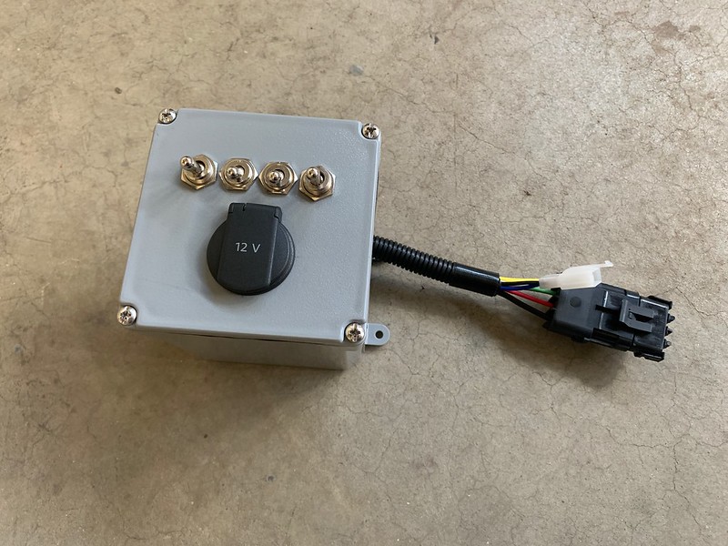
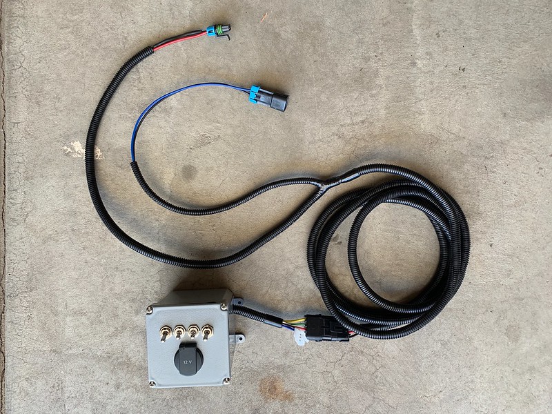
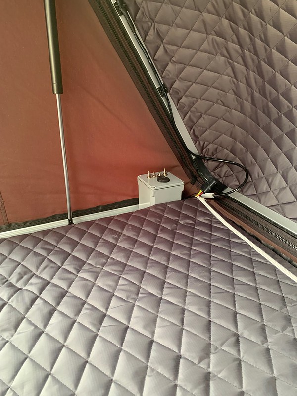
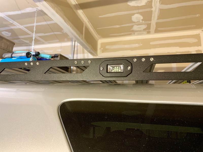
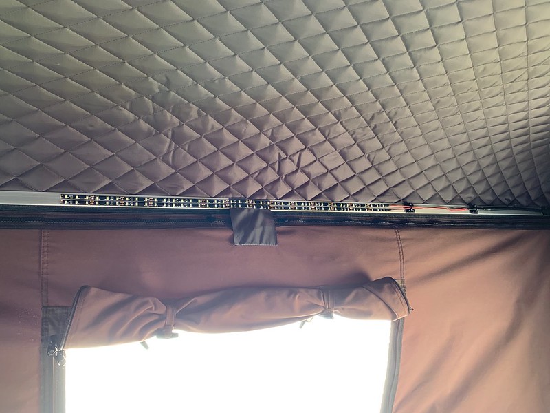
The roof rack camping lights are wired with a connection at the front of the roof along the inside edge of the side rails. I made the tent harness so it can be plugged in, in-line, at that connection. With the rooftop tent box wired in series, turning on the dash switch for the right side lights powers up the box. The tent box contains its own internal fuse block that powers circuits for a power outlet, red interior lights, white interior lights and controls the right side roof rack lights.
Once it was all together, weatherproofed, and verified functional, I performed voltage drops on each connection to confirm everything was operating as intended with no unforeseen power losses. At this point the system has performed flawlessly for years. I had originally built it to be expandable and since its completion, it has grown. The tent box now houses an electronic thermostat for a Propex forced air propane heater which is powered off the PDM. There is also a rear fog light, and a rear view camera and license plate light relocation that came along with the rear bumper change.
Project Objectives
Phase 1 – Single Battery
- Design and build a custom, weather-sealed, plug-and-play, expandable, adaptable, color-coded Power Distribution Module to power any and all non-OEM electrical loads and accessories
- PDM will be controlled by a custom switch panel
- PDM will be fed power through a low voltage disconnect that will cut power when the voltage of the single battery drops below a preset value in order to preserve battery life and ensure reliable starting
- Roof top tent will have internal and external lights and 12v power
Phase 2 – Dual Battery
- Expand the Phase 1 design to incorporate a second battery, completely isolated from the starter battery, to power any and all non-OEM electrical loads and accessories
- Accessory battery will have the ability to be charged via solar, AC/DC shore power, or indirectly via DC/DC while the engine is running
- All changing methods will monitor battery health and utilize different charging profiles when appropriate
Materials
Electrical Accessories
- Baja Designs Squadron Pro amber driving combo fog lights
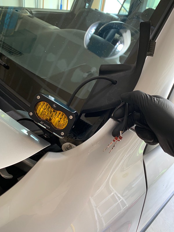
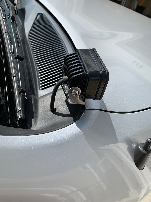
- Baja Designs S2 Pro amber wide cornering ditch lights
- Freedom Designs 5D 22” dual row light bar
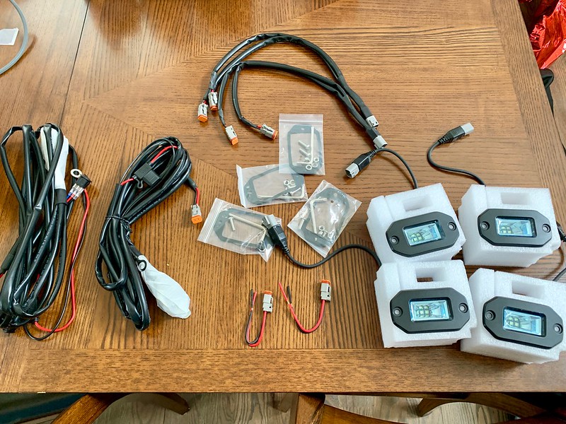
- Aurora LED 2” flush mount scene light left side camping lights
- Aurora LED 2” flush mount scene light right side camping lights
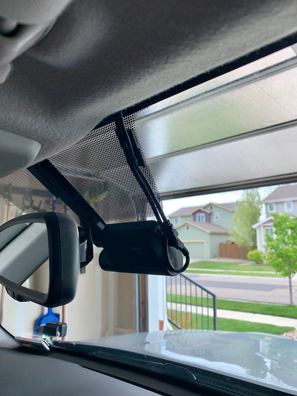
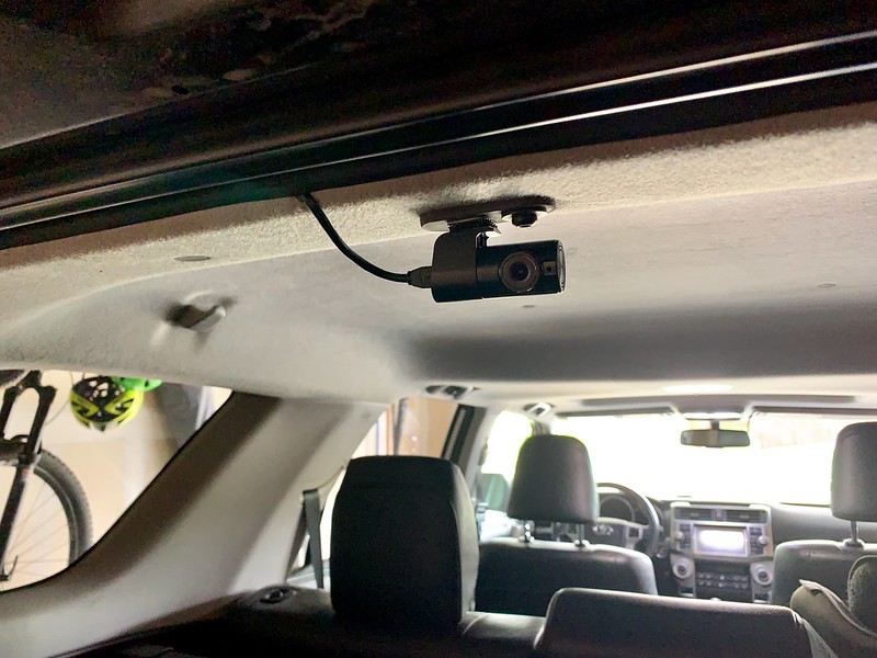
- Thinkware Q800Pro 2-channel dash cam
- Blue Sea high output USB power outlets in the center console
- 12v tent power outlet
- Red LED strip interior tent light
- White LED strip interior tent light
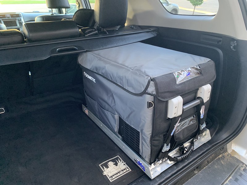
- Dometic CFX35W refrigerator/freezer
Electrical Equipment
- X2 Power (Northstar) Group 24F 76Ah/840CCA dual purpose deep cycle AGM starter battery
- Vmax Charge Tanks SLR85 Group 24 85Ah deep cycle AGM accessory battery
- Red Arc BCDC1225D DC/DC 25 amp charger with MPPT solar controller
- NoCo Gen 2 Genius 10 amp per bank dual bank AC/DC charger
- Victron BMV-712 Smart battery monitor
- Custom made dash console switch panel
- Custom made roof top tent electrical box
Electrical Parts
- Eaton Bussman 15305-5-2-4 RTMR Power Distribution Module housing
- Blue Sea 2304 100 amp 5 gang mini bus bars
- Eaton Bussman CB285-80 surface mount 80 amp circuit breaker
- Eaton Bussman CB285-40 surface mount 40 amp circuit breaker
- Blue Sea 7615 Low Voltage Disconnect
- Carling Industries V-Series Contura II rocker switches (amber LED, lower independent)
- Metri-Pack 280 Series connector housings, terminals, and weather seals
- Delphi Weather-Pack connector housings, terminals, and weather seals
- Molex Mini-Fit Jr connector housings and terminals
- Type TXL Primary Wiring (OEM Specification: Ford M1L-123A, Chrysler MS-8288, SAE J-1128)
- Marine grade dual wall adhesive lined heat shrink
- ISO 280 35 amp micro relays
- ATC blade fuses
- ATM blade fuses
- Miscellaneous cable lugs, ends, and terminals
Layout & Design
Wiring Diagram & Blueprint

Assembly & Installation
Switch panel


Power Distribution Module


Rooftop Tent Electrical Box

Dual Battery & Equipment
AC/DC Charger
Lights & Accessories

Finished Product

Project planning, design, diagram, fabrication, and installation by:
Ryan Dontsow
